A coded weld is not powered by the arc. It is powered by a procedure written before anyone lifts a stinger, and that procedure names a temperature to reach and then hold.
The first load is heat
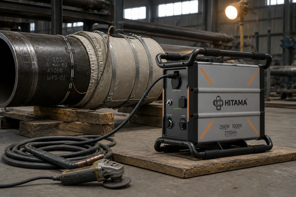
Preheat starts while the welder is still taping leads. The pads are on the joint, the controller is cycling, the machine is working before there is a single arc. If the unit is still in the van, the schedule has slipped.
Ask the welding engineer for three things: the preheat temperature, the pad set that reaches it, the controller's continuous draw. Those decide the power question; the welding current decides another.
The arc is intermittent. The heat is not. A welder stops to change a rod, grind, measure, wait for inspection. The pads do not take those breaks.
The interpass window is the expensive part
Between passes the joint may not fall below a minimum, and the machine is the only thing holding it there. The load nobody lists is not the welder's draw but the hours of holding after the last pass.
Switching off at lunch is a decision with a cost. The joint cools and the next session starts with the same heat again. On a thick section, that is the schedule.
Where two loads run at once, the sum is what matters: pads on the joint, grinder on the fit-up. One 2,500 W rated unit with a 5,000 W peak will not be talked into both — one to three modules parallel at 230 V single-phase or 400 V three-phase.
A sealed case can stand where the joint is
No intake, no exhaust, no fan, no moving parts — the case is the heat exchanger. That decides placement: the unit stands inside the vessel or under the scaffold, pulling no grinding dust through a filter and putting no exhaust plume next to a shielding gas cloud. Keep the case and the preheat blanket apart.
IP54 and −10 to 65 °C are the numbers for a bay in February: splatter, dust, a cold shell at seven in the morning. Let a cold unit reach ambient before it goes on the socket.
The check is a multiplication
Capacity per unit is fixed: 2.7 kWh on a P25, 5.4 kWh where two run as a P25-D, 8.1 kWh where three run as a P25-T at 400 V three-phase. The procedure gives the draw, the schedule gives the hours, the multiplication decides.
Charging is a separate timetable. 500–1,500 W from a 230 V socket, two hours to 80 percent and 2.5 to full on a P25. With no socket in the bay, the charge window is the constraint.
29 kg is the other number. A joint inside a vessel or up a scaffold is a carry, and the handle frame exists for it. Pure sine, THD below 3 percent, matters for the controller and the chart recorder.
Where the arc fits
The arc is the easy part, because everyone plans it. P25 carries a 160–200 A inverter welder when the set is built around the three-phase models and a distribution box. Plan both loads in one pass.
What this is not
Not a replacement for a fixed heat-treatment supply. Where the procedure calls for several circuits or a furnace panel, 2,500 W rated is the wrong answer however many are stacked.
Not an approval. CE under the EMC Directive 2014/30/EU and UN 3480 class 9 packaging cover electrical behaviour and transport. IP54 says nothing about a hazardous area, and none of it replaces the procedure or the thermocouples.
Every unit leaves through a ten-point test, IQC to the burn-in rack to final inspection — a factory statement, not a site guarantee. The site guarantee is the schedule you log.
Send the preheat and interpass lines, the controller's draw, the hold duration and the walk from the van to the joint. We will say whether it is one unit, two in parallel or a three-phase set.